

News

Miro: A New Standard in Responsible Innovation

Miro: A New Standard in Responsible Innovation The Miro monitor arm is setting new benchmarks in sustainability. It offers a high-performance solution without compromising on environmental responsibility. Designed with careful material selection, local sourcing, and longevity in mind, Miro’s responsible approach to design and unique manoeuvrability set it apart from the competition. Sustainable Choices Miro is crafted from energy-efficient materials with a lower carbon impact....

Read more
HSE Advisor

Role Purpose Support in the development, implementation and maintenance of the company’s Health, Safety & Environmental policies, processes, operational procedures, and standards.  Ensuring best practice and championing a continually improving HSE culture within the business. Key Responsibilities Liaise with and provide support to all areas of the business to eliminate, mitigate or reduce identified HSE exposures. Partner with the production management team and team leaders,...

Read more
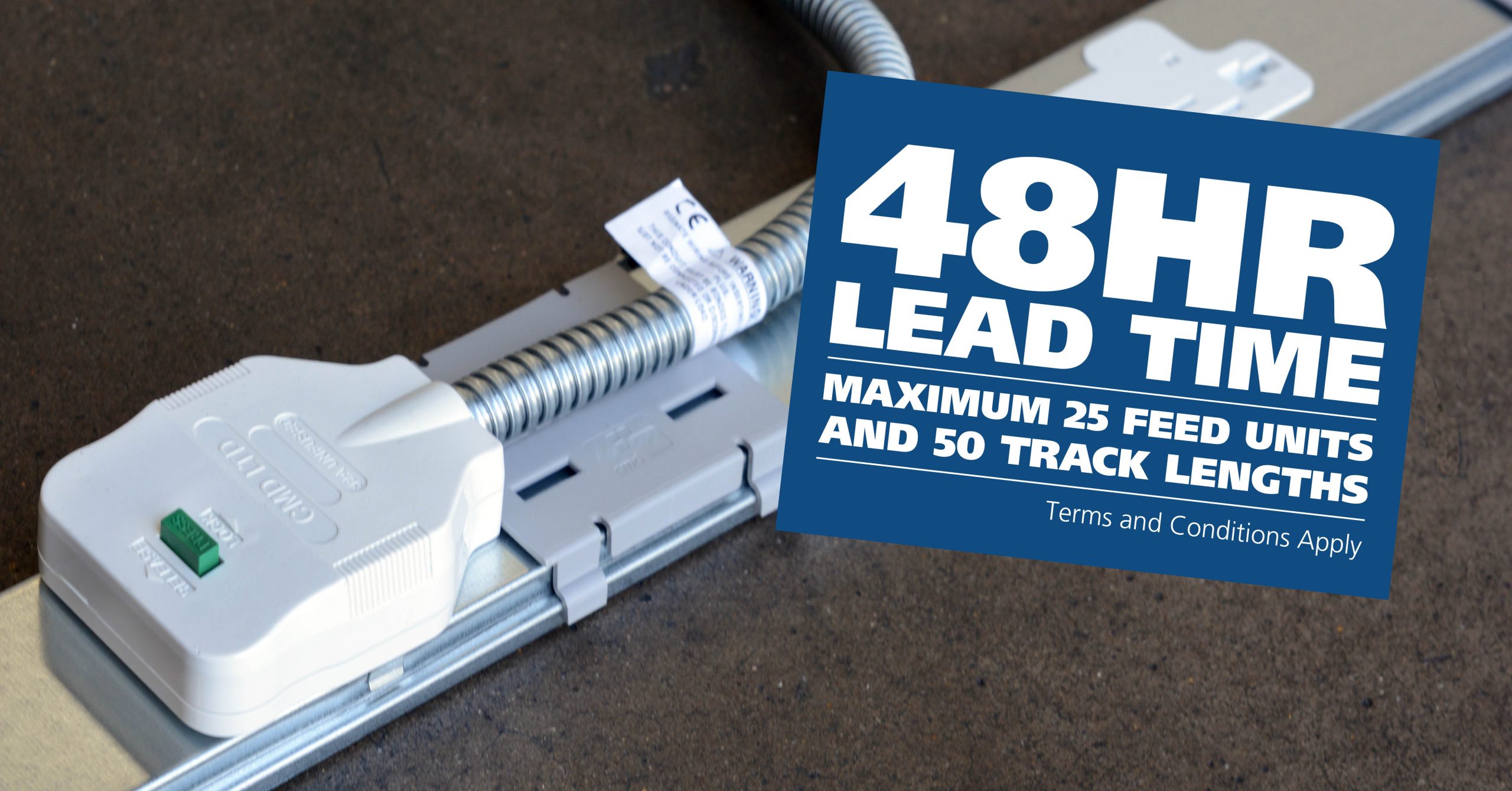
CMD Ltd LAUNCHES 48-HOUR TURNAROUND ON BETATRAK® RAPID ORDERING SERVICE

CMD Ltd, the specialist in power distribution systems, workstation power and monitor arms, has launched a rapid ordering service for its Betatrak® underfloor powertrack distribution systems and accessories, with a commitment to delivering within 48-hours of an approved purchase order*. The service enables customers to order up to 50 lengths of Standard or Clean Earth (C/E) low noise Betatrak, along with up to 25 feed...

Read more
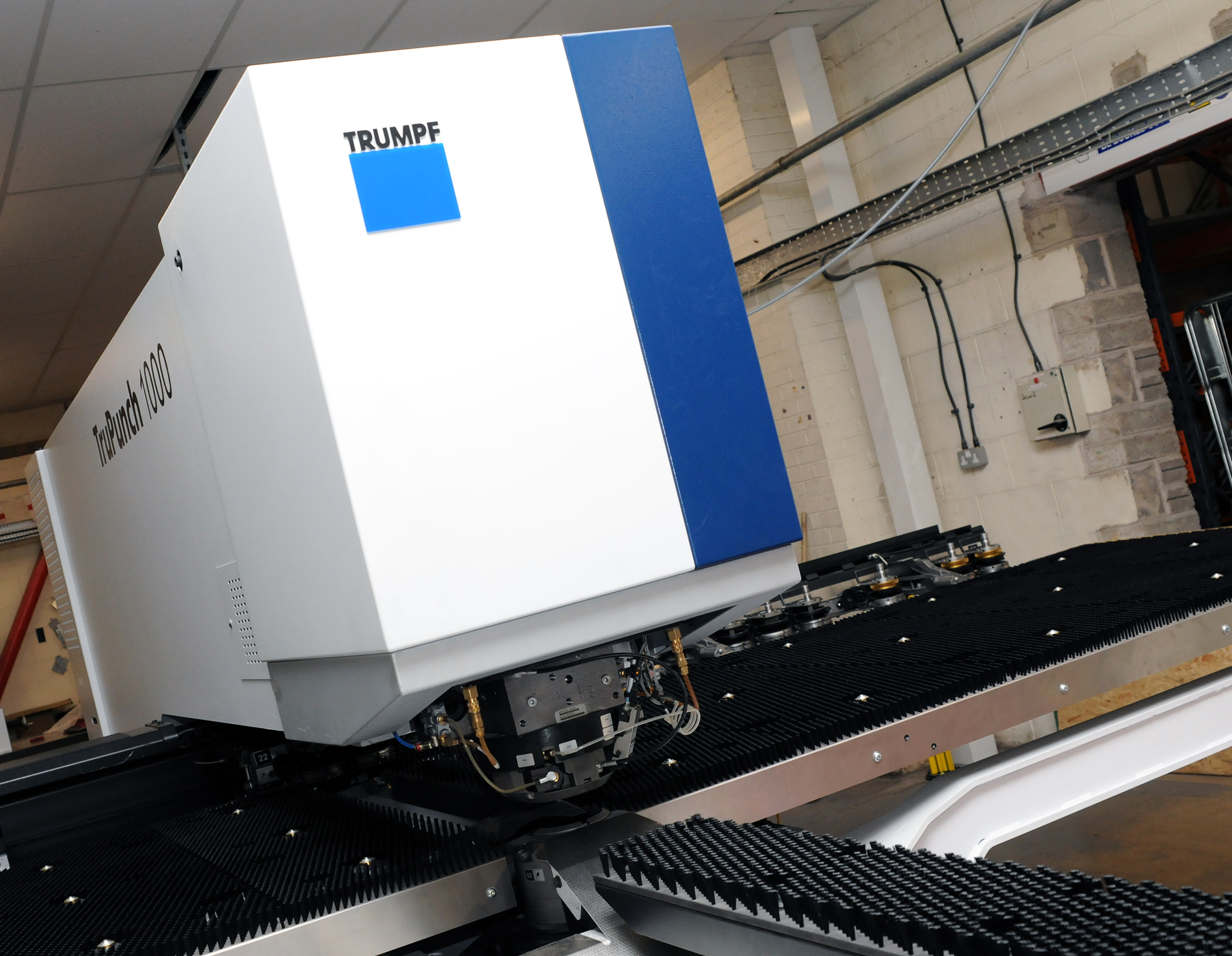
CMD INVESTS £1/4 MILLION IN NEW MACHINE AS PART OF FACTORY UPGRADE

We have invested in a new £1/4m TRUMPF CNC metal punch as part of an asset renewal strategy for our UK manufacturing capability. The new machine will be used in the production of a wide variety of our power distribution systems and workstation power products at our Rotherham factory. Suitable for handling sheet metal between 0.9mm and 3.0mm thick, the new machine will replace one...

Read more
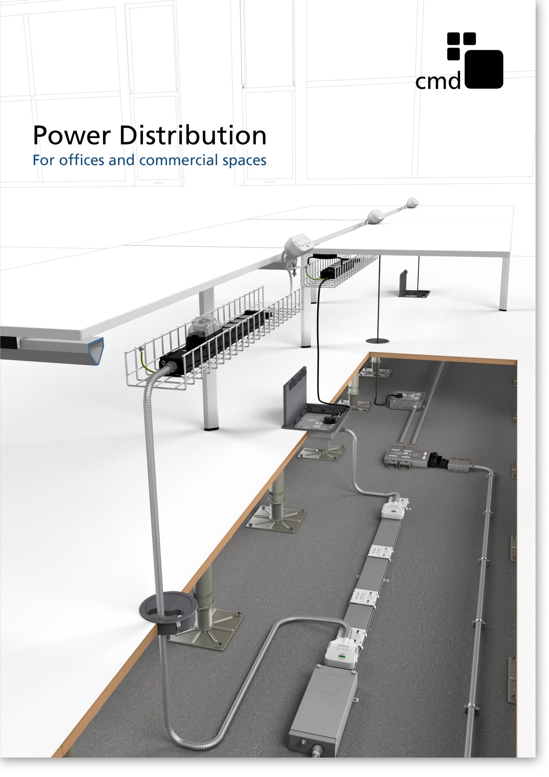
CMD CATALOGUE PROVIDES TECHNICAL POWER DISTRIBUTION GUIDE

CMD Ltd has released a new catalogue, providing an easy to follow technical guide to our power distribution systems and plug and play desk modules. Detailing CMD’s full range of UK-manufactured power distribution systems and plug and play desk modules, the catalogue will be a helpful source of information to M&E engineers and contractors alike to understand how our power distribution systems connect together and...

Read more
Power Distribution Catalogue
CMD Ltd PLAYS ESSENTIAL ROLE IN ELECTRICAL FIT OUT AT LONDON’S PRESTIGIOUS OFFICE DEVELOPMENT

CMD Ltd, specialist in workplace connectivity and ergonomic solutions, has provided a flexible and high-quality power distribution network for The Ray, a prestigious office development in London’s Farringdon. Well-known for being the former site of The Guardian newspaper, The Ray now stands as an 83,000ft² office development characterised by a modernised warehouse aesthetic, with level two now occupied by a global social media company. The...

Read more

The Ray
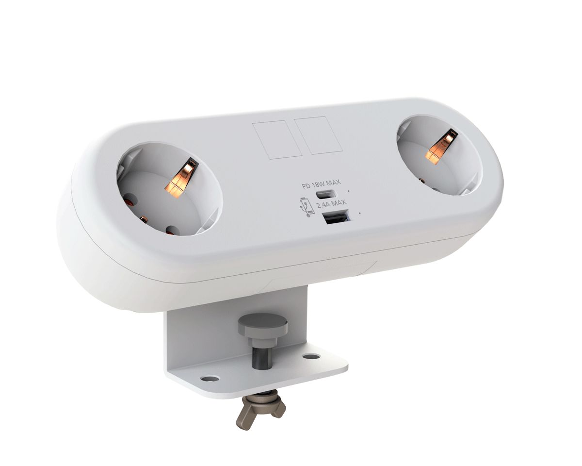
CMD plugs in to european opportunity with Schuko Capsule unit launch

CMD Ltd, the specialist in power and connectivity solutions for commercial environments, has launched a Schuko version of its popular fixed format Capsule workstation power module for export to mainland Europe and beyond. A popular on desk power module comprising two sockets and dual USB (type A and C) chargers, CMD’s Capsule unit is already widely specified in the UK as an off-the-shelf workstation power...

Read more
CMD White Schuko Capsule Desk Power Module
CMD LTD EXTENDS MONITOR ARM RANGE WITH THE LAUNCH OF REACH PLUS

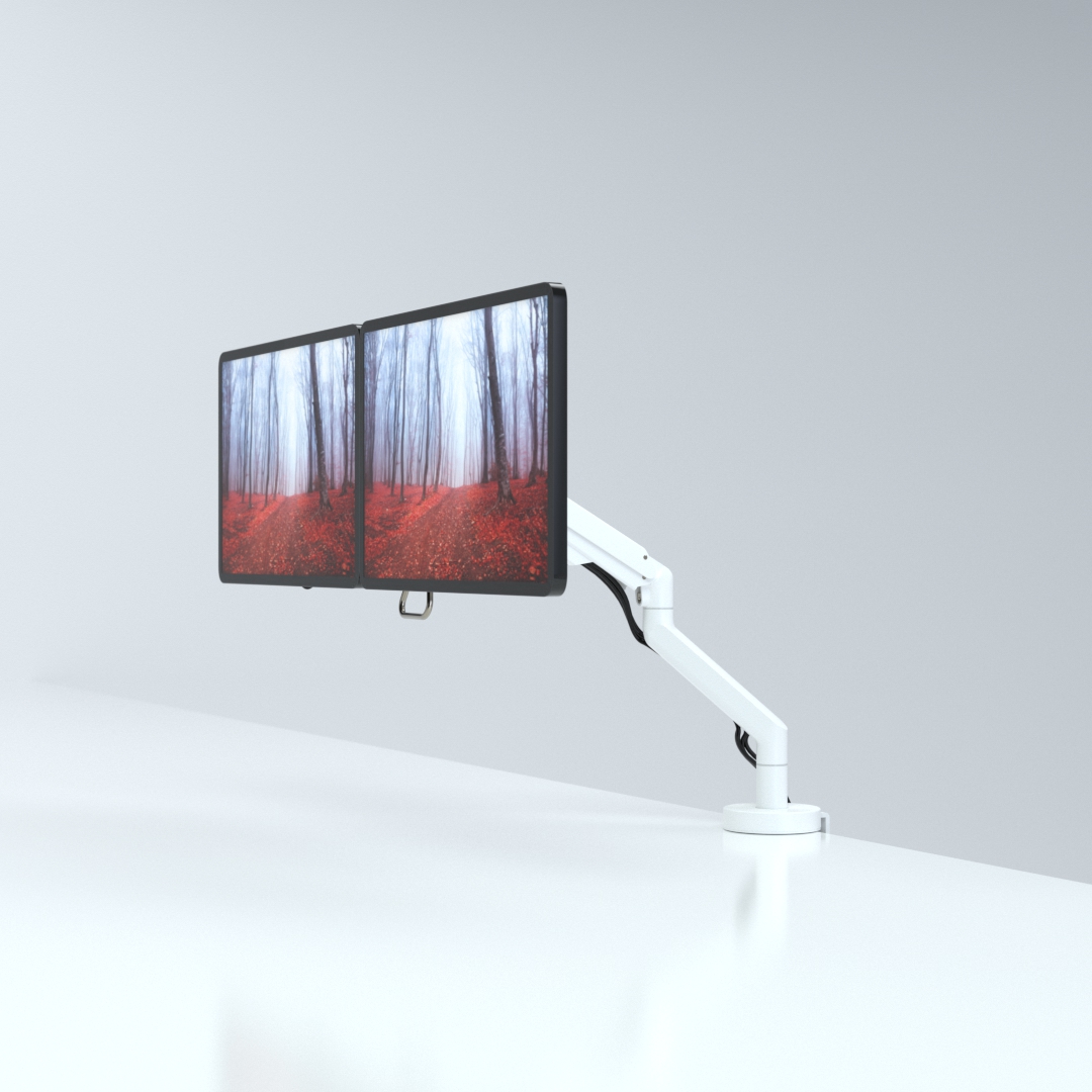
CMD Ltd, the specialist in ergonomic and connectivity solutions for commercial interiors, has completed its Reach monitor arm range with the launch of the Reach Plus. Available in single or dual screen options, the Reach Plus has been designed to provide an ideal solution for both single and dual screen workstation configurations, or can be used with next generation of large format curved screens. Suitable...

Read more
CMD Ltd DEMONSTRATES THE ART OF POWER DISTRIBUTION AT THE UNIVERSITY OF WARWICK

CMD Ltd, the specialist in workplace connectivity and ergonomic solutions, has provided Betatrak busbar power distribution and a range of electrical accessories for two major capital investment projects at the University of Warwick. Designed by Fielden Clegg Bradley Studios, the £33 million Faculty of Arts building is a showpiece development comprising four interconnected structures set around a central atrium, which will enable inter-disciplinary collaboration across...

Read more

University of Warwick
CMD BRINGS HARMONY TO COVENTRY UNIVERSITY RESEARCH FACILITIES

CMD Ltd, the specialist in power distribution solutions and workstation power and ergonomics, has provided under desk and on desk power modules for the refurbishment of three Coventry University research buildings. Located on Coventry University Technology Park, a business park designed to encourage collaboration between the university and knowledge-based businesses, the three buildings are being repurposed as office accommodation for university research teams. The refurbishment...

Read more

Coventry University

What Are Optical Cable Adapters and How Do They Work?

Optical Cable Adapters are small components that help connect two fiber optic cables or devices securely. They are commonly called fiber adapters, couplers, or mating sleeves. Their main purpose is alignment, not signal amplification. Inside each adapter, a precision sleeve holds two connector ferrules in line. This alignment allows light to pass through the fiber cores with minimal disruption.

Different connector types require different adapters. LC, SC, ST, and FC connectors each have distinct shapes and locking methods. Simplex adapters connect one fiber, while duplex models connect two fibers side by side. Some versions include flanges, mounting clips, or metal bodies for demanding network environments. A technician may install them in a patch panel, wall outlet, distribution box, or testing setup.

The working principle is straightforward, but real installations can be less forgiving. Dust on a ferrule end face may increase insertion loss or cause unstable readings. Small alignment errors can also reduce optical performance. For this reason, experienced installers inspect, clean, and test connectors before mating them. They may use a fiber inspection microscope, cleaning cassette, and optical power meter. The adapter itself does not repair a damaged cable. That point is often overlooked.

A reliable explanation should also recognize practical limits. Adapter quality, connector polish, sleeve tolerance, and installation technique all affect results. Even a correctly selected adapter may perform poorly in a contaminated enclosure. This guide examines how Optical Cable Adapters work, where they are used, and what professionals should check before installation. The process sounds simple. It still demands care.

What Are Optical Cable Adapters and How Do They Work?

What Optical Cable Adapters Are

An optical cable adapter is a small passive component that joins two fiber-optic connectors. It is often called a fiber adapter or coupling sleeve. Inside, a precision sleeve holds the connector ferrules in line, helping light pass from one fiber end to the other. The adapter does not amplify or convert the signal. Its job is alignment.

Adapters commonly fit into panels, wall outlets, or equipment enclosures. Some connect a single pair of fibers; duplex versions hold two connections side by side. Their ends must match the connector style and polish being used. A mismatch can prevent a proper fit or increase signal loss. Dust matters, too. A tiny particle on a ferrule can interfere with the light path, even when the adapter looks clean. It is easy to assume all adapters are interchangeable, but that assumption can lead to frustrating installation problems.

Tips: Check connector type and fiber mode before ordering. Inspect and clean connector end faces with suitable tools. Seat each plug gently, without forcing it. If readings are unexpectedly poor, recheck alignment and cleanliness before replacing parts. A little uncertainty is normal; test the connection rather than relying on appearance alone.

The Main Parts and Connector Types

An optical cable adapter is a small alignment device that joins two fiber connectors. Its outer housing holds the connectors steady, while a precision sleeve inside aligns their ferrules. The ferrules guide light through tiny glass cores. Even slight misalignment can increase signal loss.

Small parts matter.

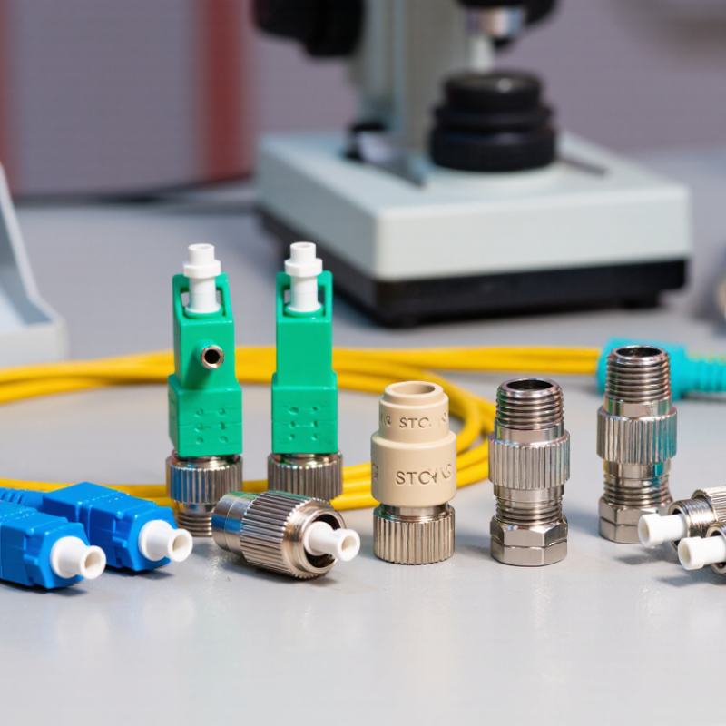
Adapter sleeves are commonly ceramic or metal, depending on the design and application. A retaining clip or threaded fitting may secure the adapter in a panel or enclosure.

Connector shape determines which adapter you need.

SC connectors use a square push-pull body; LC connectors are smaller and often fit densely packed panels. ST connectors lock with a twist, while FC connectors use a threaded coupling.

Simple distinctions, but easy to overlook. Adapters may connect simplex or duplex cables, and they must match the connector’s polish and fiber type. For example, angled and flat-polished endfaces should not be treated as interchangeable.

Before installation, check the connector labels and inspect the endfaces for dust. A clean-looking connector can still carry debris. That detail is often missed.

How Optical Cable Adapters Align Fiber Cores

An optical cable adapter joins two fiber connectors while keeping their ends aligned. Inside the adapter, a precision sleeve guides the connectors’ ferrules toward the same centerline. Each ferrule holds a narrow glass fiber, whose core may be only a few micrometers wide. The goal is to bring the cores close enough that light crosses the connection with minimal loss. The adapter does not correct poor cable termination.

Tiny offsets matter. If the cores sit slightly apart or at an angle, some light misses the receiving fiber. A small air gap, a scratched end face, or dust can also increase signal loss. Many adapters use a split sleeve that gently centers both ferrules as they meet. The sleeve must fit closely, but not so tightly that insertion damages the connector. Alignment quality depends on the adapter, connector condition, and how carefully the parts are handled.

During installation, connectors should meet straight and without force. A snug connection is useful; resistance or wobble deserves attention. Cleanliness matters too. Even a speck on a fiber end can be large beside the core, so inspect and clean end faces with suitable tools before mating them. It is tempting to blame an adapter when readings look poor, but a dirty connector can produce the same symptom. A clean, stable fit is a better starting point than guesswork.

How Signals Travel Through an Adapter

An optical cable adapter is a small mechanical component that joins two fiber connectors. It does not create, amplify, or translate the optical signal. Instead, it holds both connector tips in precise alignment. The adapter’s internal sleeve keeps the fiber cores facing each other with minimal lateral movement. Even a tiny offset can increase signal loss.

Inside the cable, information travels as rapid pulses of light. A transmitter sends these pulses through the fiber core. When the light reaches the adapter, it crosses a very short air gap or contact point between polished fiber ends. The receiving fiber captures the light and carries the pulses forward. The process is passive and nearly instantaneous. Nothing is electronically processed inside the adapter.

Alignment quality matters greatly. Keyed connector shapes prevent incorrect rotation, while retaining clips maintain stable pressure. Dust, scratches, or an imperfect polish can scatter light and raise insertion loss. Technicians usually inspect and clean connector end faces before mating them. It sounds simple, but real installations are less perfect. A loose panel or repeated reconnection may shift the connection slightly. Testing with an optical power meter can reveal losses that visual inspection misses. I have found that clean alignment often matters more than the adapter’s appearance. Small details decide whether a link remains stable over distance.

What Are Optical Cable Adapters and How Do They Work?

How Signals Travel Through an Adapter

An optical cable adapter is a passive component that aligns two fiber connectors so light can pass from one fiber core to the other. The adapter does not amplify or convert the signal; a small reduction in received power is caused by connector alignment, air gaps, and microscopic contamination. This representative single-mode link budget starts at 0 dBm and shows a typical adapter insertion loss of about 0.3 dB.

How to Choose and Maintain an Optical Cable Adapter

Optical cable adapters, often called couplers, align two fiber connectors inside a precision sleeve. They do not amplify light. They preserve the optical path by centering both ferrules with tiny mechanical tolerances. Common types include single-mode, multimode, simplex, duplex, and angled-contact versions. Choosing the wrong type can create high insertion loss or unwanted reflections.

Check connector geometry before purchasing. A flat-polished adapter cannot replace an angled-contact adapter in every link. The Fiber Optic Association reports typical connector loss near 0.2–0.5 dB under clean, well-mated conditions. That figure is useful, but field results can be worse. Inspect the end face with a fiber microscope, then clean it with approved lint-free materials. Never trust a cap that only looks clean.

Match the adapter to the cable, enclosure, and environment. For outdoor systems, select sealed construction and suitable temperature ratings. For dense racks, verify polarity, latch strength, and port labeling. IEC 61300-3-35 provides inspection guidance for connector end faces, while IEC 61300 test methods address optical performance and environmental reliability. Keep unused ports capped. Avoid repeated mating. It wears the alignment sleeve. I have seen a stable link fail after one careless cleaning cycle, usually because contamination was pushed deeper. Record insertion-loss readings during commissioning and after maintenance. Small records prevent large guesses.