

News

Miro: A New Standard in Responsible Innovation

Miro: A New Standard in Responsible Innovation The Miro monitor arm is setting new benchmarks in sustainability. It offers a high-performance solution without compromising on environmental responsibility. Designed with careful material selection, local sourcing, and longevity in mind, Miro’s responsible approach to design and unique manoeuvrability set it apart from the competition. Sustainable Choices Miro is crafted from energy-efficient materials with a lower carbon impact....

Read more
HSE Advisor

Role Purpose Support in the development, implementation and maintenance of the company’s Health, Safety & Environmental policies, processes, operational procedures, and standards.  Ensuring best practice and championing a continually improving HSE culture within the business. Key Responsibilities Liaise with and provide support to all areas of the business to eliminate, mitigate or reduce identified HSE exposures. Partner with the production management team and team leaders,...

Read more
CMD Ltd LAUNCHES 48-HOUR TURNAROUND ON BETATRAK® RAPID ORDERING SERVICE

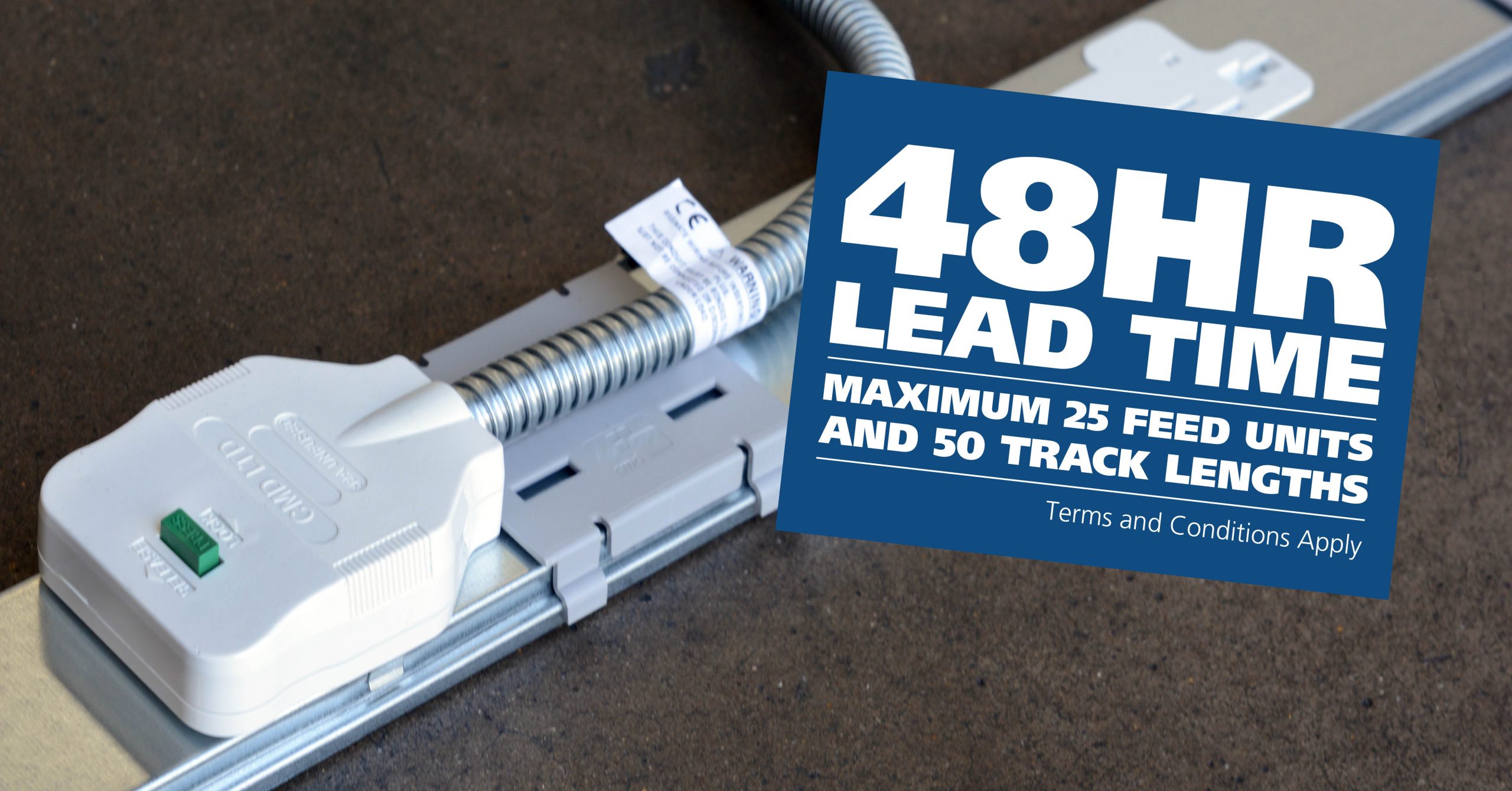
CMD Ltd, the specialist in power distribution systems, workstation power and monitor arms, has launched a rapid ordering service for its Betatrak® underfloor powertrack distribution systems and accessories, with a commitment to delivering within 48-hours of an approved purchase order*. The service enables customers to order up to 50 lengths of Standard or Clean Earth (C/E) low noise Betatrak, along with up to 25 feed...

Read more
CMD INVESTS £1/4 MILLION IN NEW MACHINE AS PART OF FACTORY UPGRADE

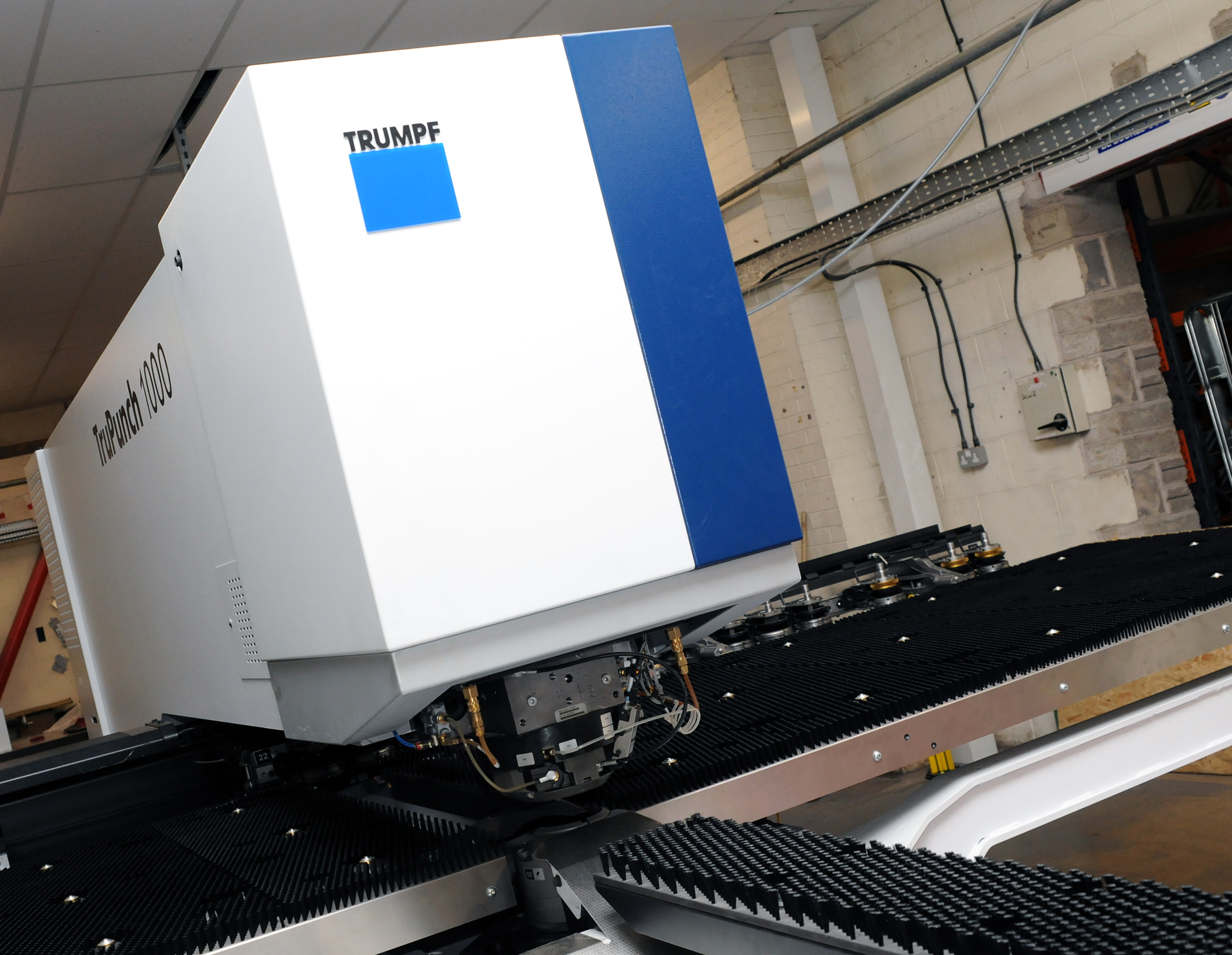
We have invested in a new £1/4m TRUMPF CNC metal punch as part of an asset renewal strategy for our UK manufacturing capability. The new machine will be used in the production of a wide variety of our power distribution systems and workstation power products at our Rotherham factory. Suitable for handling sheet metal between 0.9mm and 3.0mm thick, the new machine will replace one...

Read more
CMD CATALOGUE PROVIDES TECHNICAL POWER DISTRIBUTION GUIDE

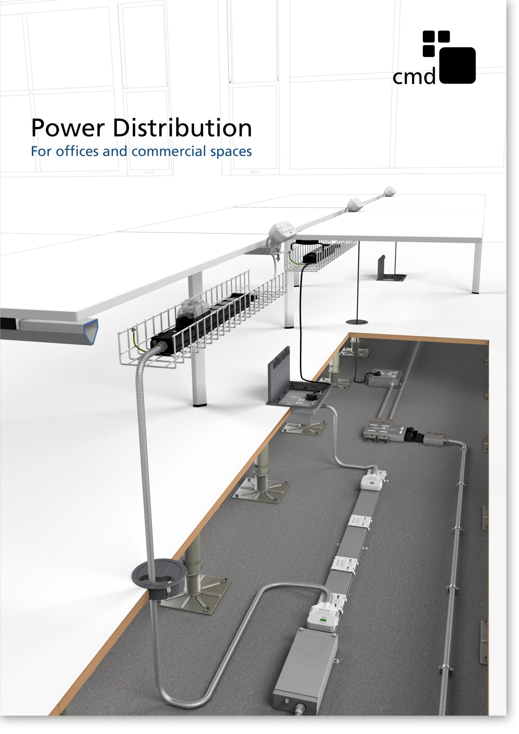
CMD Ltd has released a new catalogue, providing an easy to follow technical guide to our power distribution systems and plug and play desk modules. Detailing CMD’s full range of UK-manufactured power distribution systems and plug and play desk modules, the catalogue will be a helpful source of information to M&E engineers and contractors alike to understand how our power distribution systems connect together and...

Read more
Power Distribution Catalogue
CMD Ltd PLAYS ESSENTIAL ROLE IN ELECTRICAL FIT OUT AT LONDON’S PRESTIGIOUS OFFICE DEVELOPMENT

CMD Ltd, specialist in workplace connectivity and ergonomic solutions, has provided a flexible and high-quality power distribution network for The Ray, a prestigious office development in London’s Farringdon. Well-known for being the former site of The Guardian newspaper, The Ray now stands as an 83,000ft² office development characterised by a modernised warehouse aesthetic, with level two now occupied by a global social media company. The...

Read more

The Ray
CMD plugs in to european opportunity with Schuko Capsule unit launch

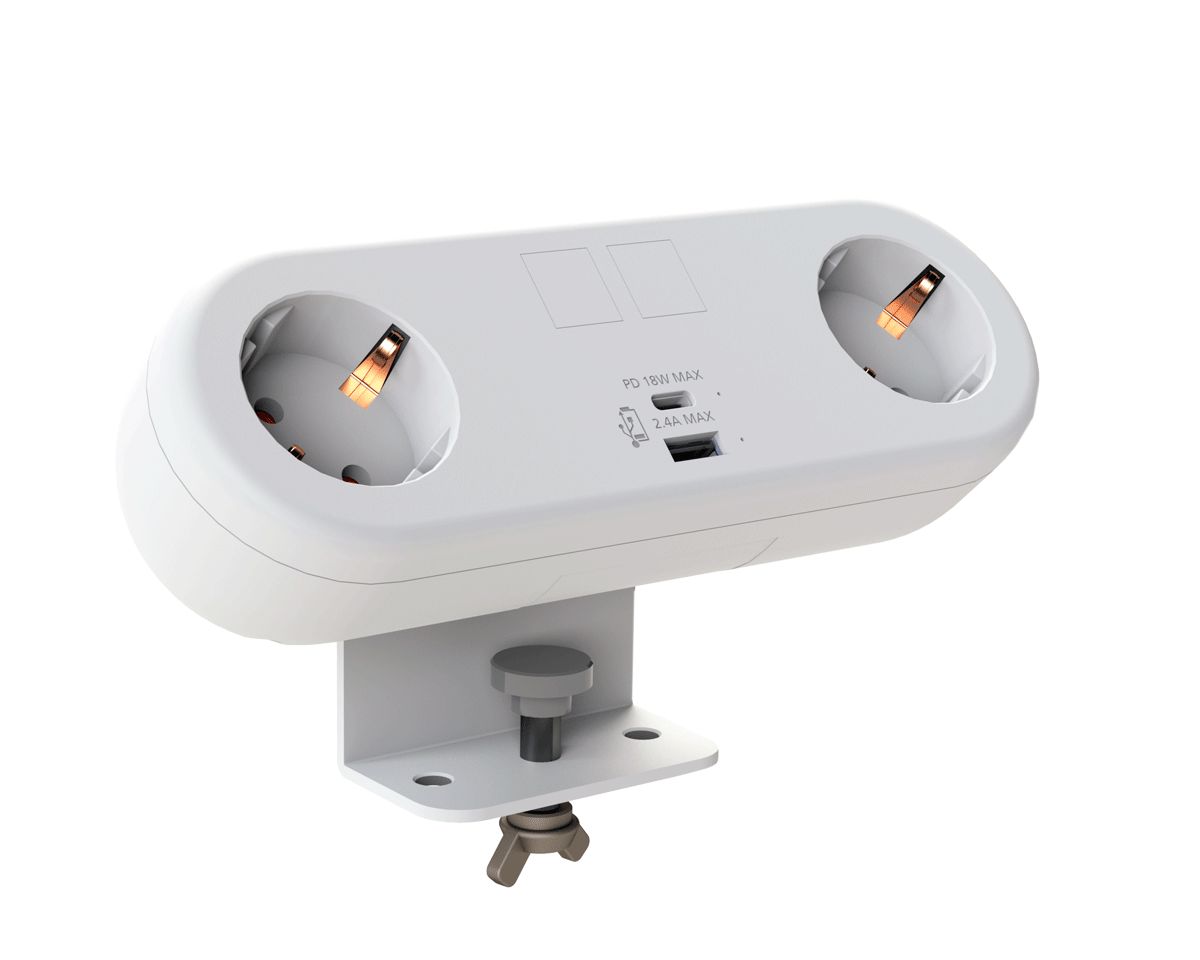
CMD Ltd, the specialist in power and connectivity solutions for commercial environments, has launched a Schuko version of its popular fixed format Capsule workstation power module for export to mainland Europe and beyond. A popular on desk power module comprising two sockets and dual USB (type A and C) chargers, CMD’s Capsule unit is already widely specified in the UK as an off-the-shelf workstation power...

Read more
CMD White Schuko Capsule Desk Power Module
CMD LTD EXTENDS MONITOR ARM RANGE WITH THE LAUNCH OF REACH PLUS

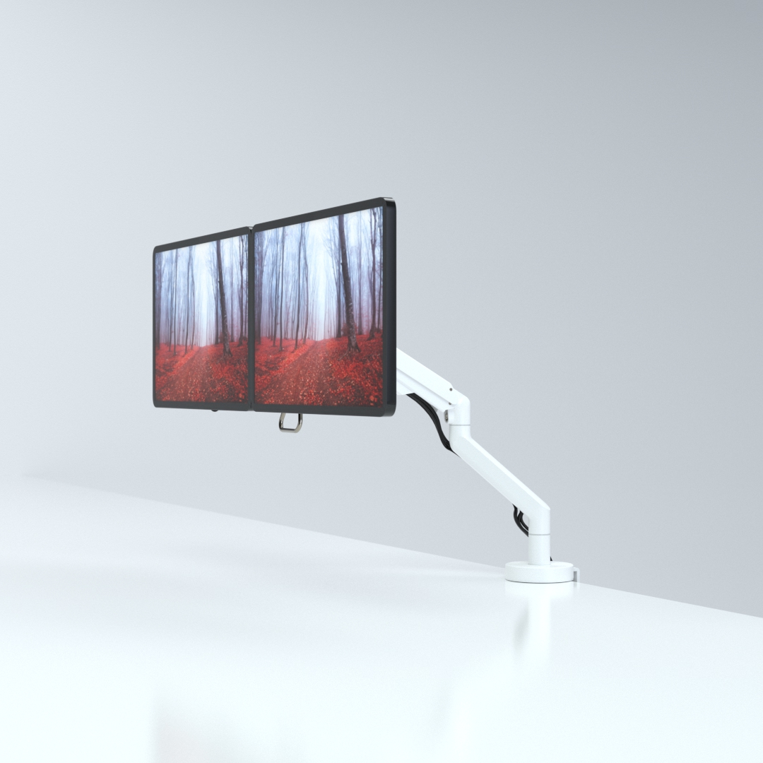
CMD Ltd, the specialist in ergonomic and connectivity solutions for commercial interiors, has completed its Reach monitor arm range with the launch of the Reach Plus. Available in single or dual screen options, the Reach Plus has been designed to provide an ideal solution for both single and dual screen workstation configurations, or can be used with next generation of large format curved screens. Suitable...

Read more
CMD Ltd DEMONSTRATES THE ART OF POWER DISTRIBUTION AT THE UNIVERSITY OF WARWICK

CMD Ltd, the specialist in workplace connectivity and ergonomic solutions, has provided Betatrak busbar power distribution and a range of electrical accessories for two major capital investment projects at the University of Warwick. Designed by Fielden Clegg Bradley Studios, the £33 million Faculty of Arts building is a showpiece development comprising four interconnected structures set around a central atrium, which will enable inter-disciplinary collaboration across...

Read more

University of Warwick
CMD BRINGS HARMONY TO COVENTRY UNIVERSITY RESEARCH FACILITIES

CMD Ltd, the specialist in power distribution solutions and workstation power and ergonomics, has provided under desk and on desk power modules for the refurbishment of three Coventry University research buildings. Located on Coventry University Technology Park, a business park designed to encourage collaboration between the university and knowledge-based businesses, the three buildings are being repurposed as office accommodation for university research teams. The refurbishment...

Read more

Coventry University

What Is an FPGA Chip and How Does It Work?

An Fpga Chip is a reconfigurable semiconductor device that can be programmed for specific digital tasks. Unlike a fixed-function processor, it allows engineers to reshape internal hardware after manufacturing. This flexibility makes FPGAs useful in telecommunications, industrial control, medical equipment, automotive systems, and scientific instruments.

Inside an Fpga Chip, configurable logic blocks perform Boolean operations and store temporary results. Programmable routing channels connect these blocks across the silicon. Engineers describe the desired circuit with hardware languages such as VHDL or Verilog. A synthesis tool converts that description into a configuration file. The file then programs lookup tables, flip-flops, memory blocks, and input-output resources. Tiny switches change the signal paths.

That process supports parallel execution. Several operations can run during one clock cycle, often reducing latency in demanding applications. A processor usually follows instructions in sequence. An FPGA can build a pipeline that moves data through multiple stages, like parts moving along a factory line. However, flexibility does not guarantee better performance. Development can require specialized knowledge, careful timing analysis, and repeated hardware testing.

Real projects also expose practical limitations. An FPGA may consume more power than a custom chip for the same task. It can cost more than a microcontroller in simple designs. The comparison is not always clean. Device families differ greatly in speed, memory, power use, and software support. Understanding how an Fpga Chip works therefore requires more than memorizing its architecture. It requires examining the design goal, workload, operating environment, and evidence from actual measurements.

What Is an FPGA Chip and How Does It Work?

FPGA Chip Definition and Core Characteristics

What Is an FPGA Chip and How Does It Work?

FPGA Chip Definition and Core Characteristics

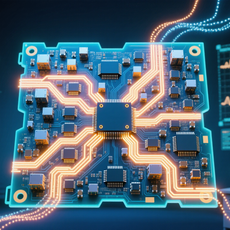
An FPGA, or field-programmable gate array, is a semiconductor device configured after manufacturing. Unlike a fixed circuit, it can be rewired for a specific task. Its internal structure usually includes configurable logic blocks, routing channels, memory elements, and input/output circuits. Small lookup tables perform logic operations, while flip-flops store values on clock edges. These parts work together through programmable connections.

Engineers describe the design with hardware languages, then convert it into a configuration file called a bitstream. The bitstream sets logic functions and routing paths inside the chip. For example, an FPGA can receive sensor samples, process several values in parallel, and send results within predictable clock cycles. This parallel structure often reduces latency. It also supports hardware updates without redesigning the physical circuit.

Flexibility is a core characteristic, but it is not unlimited. Available logic cells, memory, pins, and routing resources constrain the design. Timing closure can become difficult when signals travel across a crowded layout. Power use may also increase when many circuits switch simultaneously. I once treated reconfigurability as an automatic advantage, but that view was incomplete. A poorly planned design can waste resources and perform worse than a simpler circuit. Careful clock planning, simulation, and hardware testing remain essential. Real measurements matter.

FPGA Architecture: Logic Blocks, Routing, and Input/Output

What Is an FPGA Chip and How Does It Work?

An FPGA is a reconfigurable chip built from three main systems: logic blocks, routing resources, and input/output circuits. Unlike a fixed-purpose chip, it can be programmed to perform different digital tasks after manufacturing. In practical testing, the architecture feels like a large electronic workshop. Each logic block handles a small operation, while the routing network connects those operations into a working design.

Logic blocks usually contain lookup tables, registers, and control elements. A lookup table can produce a chosen output from several input patterns. Registers store values between clock cycles, which helps create counters, pipelines, and state machines. My first mental model treated these blocks as independent calculators. That was incomplete. Their real strength comes from coordinated timing and carefully planned connections.

Routing resources act like programmable wiring across the chip. They carry signals between logic blocks, memory areas, and I/O pins. Good routing reduces delay and prevents congestion. Poor routing can make a correct design run slowly.

Input/output circuits connect internal logic with sensors, displays, memory devices, or other electrical systems. They also manage voltage levels, signal timing, and data direction. Small timing errors matter. A design may simulate correctly yet fail on a physical board because signals arrive too late. Careful testing, timing analysis, and measured hardware observations make FPGA results more reliable.

How FPGA Configuration and Reprogramming Work

An FPGA is configured by loading a digital design file called a bitstream. This file sets the behavior of logic blocks, signal routes, memory elements, and input-output circuits. Unlike fixed hardware, an FPGA can change after manufacturing. That flexibility is its main practical advantage.

During configuration, a controller transfers the bitstream into configuration memory. Many devices use volatile memory, so they need a fresh configuration after power is removed. Nonvolatile storage can reload it automatically during startup. The process also checks timing, data integrity, and configuration status. A single corrupted bit may create an intermittent fault, which is difficult to diagnose. Careful verification matters.

Reprogramming usually happens through a debugging port, a processor, or an external memory device. Engineers revise hardware description language code, synthesize it, place and route the design, then generate a new bitstream. The FPGA may be fully reconfigured or updated in selected regions while other logic continues running. Partial updates save time, but they demand strict isolation between changing and active circuits. In laboratory testing, a design can work perfectly at room temperature and still fail under voltage variation. That result is a useful warning: simulation is evidence, not proof. Configuration files should be versioned, protected from accidental changes, and tested on the actual board. The workflow is powerful, but not effortless.

The Step-by-Step Process of Running Designs on an FPGA

An FPGA is a programmable chip built from configurable logic blocks, memory, and routing channels. Unlike a fixed-function processor, it can become a custom digital circuit. The design begins with a hardware description, schematic, or graphical logic model. Engineers define functions such as counters, filters, or communication interfaces.

A typical workflow starts with writing and checking the design. Simulation helps reveal incorrect logic before hardware testing. The development tool then synthesizes the description into basic logic elements. Next, it maps those elements onto available resources inside the FPGA. Placement assigns physical locations, while routing connects them with internal wires. Timing analysis checks whether signals arrive quickly enough. The tool generates a configuration file, often called a bitstream. This file is loaded into the FPGA through a programming interface. After configuration, input pins, clocks, and internal signals begin driving the circuit. The FPGA executes these operations in parallel, not as a simple instruction list. A design may pass simulation but fail on the board because of timing, noise, or an overlooked reset condition. That gap requires careful measurement and revision.

Tips: Keep clock planning simple. Add reset logic early. Check timing reports, not only functional results. Use visible test signals when debugging. The first build is rarely perfect. Leave room for correction.

Common FPGA Applications and Key Advantages

An FPGA is a reconfigurable chip built from programmable logic blocks, routing channels, and memory elements. Engineers describe its hardware behavior with specialized design languages. The device then configures itself after power-up. Unlike a fixed processor, it can run many operations in parallel. That difference matters.

Common FPGA applications include industrial machine vision, wireless infrastructure, medical imaging, robotics, and high-speed financial data processing. In a factory, an FPGA can inspect several camera feeds while controlling motors with predictable timing. In edge systems, it can filter sensor data locally, reducing network traffic and response delays. A 2024 FPGA market forecast estimates global revenue will grow from 9.8 billion dollars in 2024 to 19.3 billion dollars in 2029, representing a 14.5% compound annual growth rate. The forecast is useful, but not guaranteed.

Key advantages include low-latency processing, flexible hardware updates, strong parallel performance, and long product support cycles. FPGAs can also reduce system changes when requirements evolve. Yet flexibility has a cost. Development often requires hardware expertise, careful timing analysis, and longer verification. Power efficiency may decline when designs use excessive logic or memory. In practice, the best result depends on disciplined architecture, not simply choosing a programmable chip. That point is easy to miss.

What Is an FPGA Chip and How Does It Work?

Representative timing diagram showing how programmable logic can process digital inputs through configurable logic and routing. In this example, output Y follows the logic expression A AND B.

How to read the chart: The clock provides synchronization, inputs A and B carry binary signals, and output Y changes according to the configured logic function. Unlike software running sequentially on a processor, FPGA logic blocks can operate in parallel and respond within defined clock cycles.