

News

Miro: A New Standard in Responsible Innovation

Miro: A New Standard in Responsible Innovation The Miro monitor arm is setting new benchmarks in sustainability. It offers a high-performance solution without compromising on environmental responsibility. Designed with careful material selection, local sourcing, and longevity in mind, Miro’s responsible approach to design and unique manoeuvrability set it apart from the competition. Sustainable Choices Miro is crafted from energy-efficient materials with a lower carbon impact....

Read more
HSE Advisor

Role Purpose Support in the development, implementation and maintenance of the company’s Health, Safety & Environmental policies, processes, operational procedures, and standards.  Ensuring best practice and championing a continually improving HSE culture within the business. Key Responsibilities Liaise with and provide support to all areas of the business to eliminate, mitigate or reduce identified HSE exposures. Partner with the production management team and team leaders,...

Read more
CMD Ltd LAUNCHES 48-HOUR TURNAROUND ON BETATRAK® RAPID ORDERING SERVICE

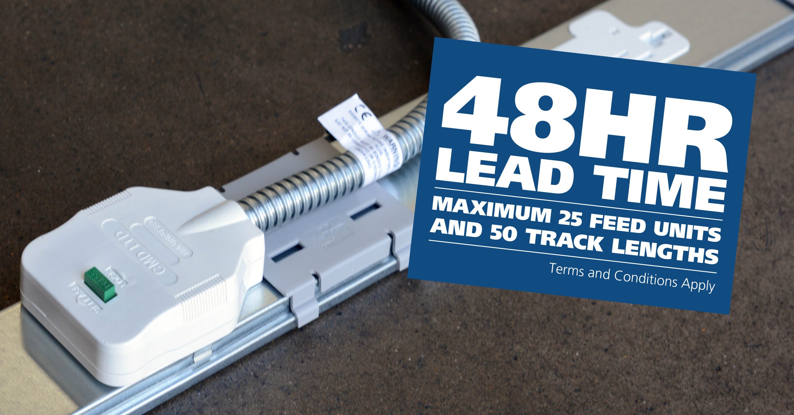
CMD Ltd, the specialist in power distribution systems, workstation power and monitor arms, has launched a rapid ordering service for its Betatrak® underfloor powertrack distribution systems and accessories, with a commitment to delivering within 48-hours of an approved purchase order*. The service enables customers to order up to 50 lengths of Standard or Clean Earth (C/E) low noise Betatrak, along with up to 25 feed...

Read more
CMD INVESTS £1/4 MILLION IN NEW MACHINE AS PART OF FACTORY UPGRADE

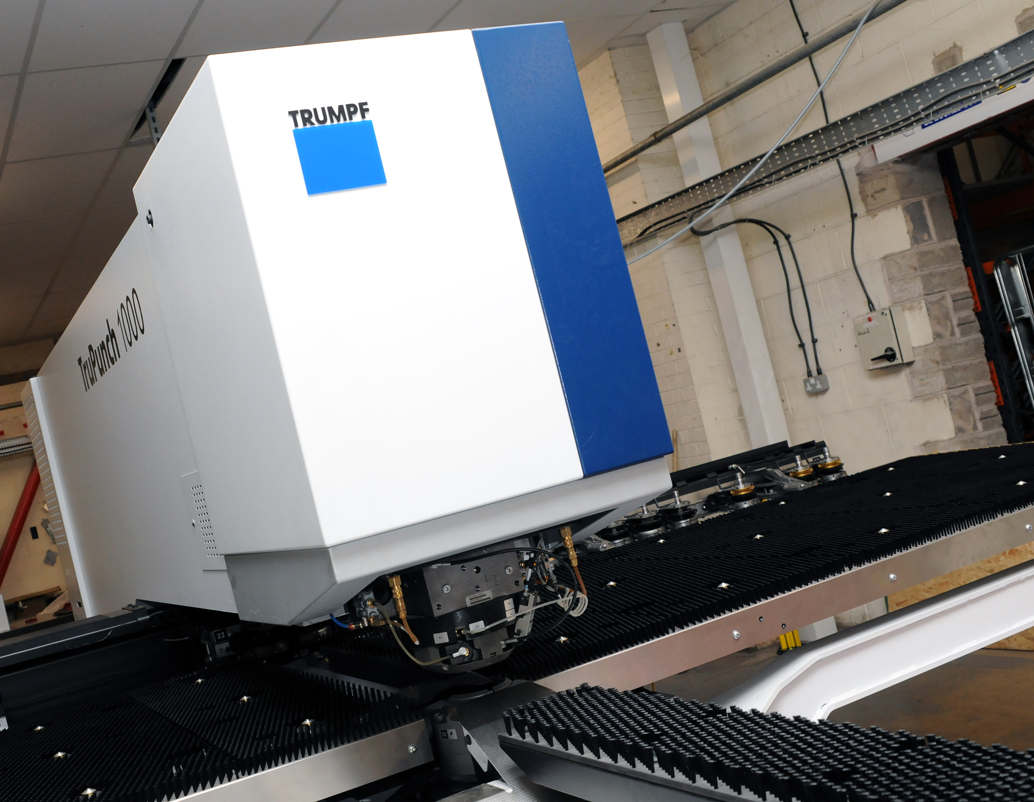
We have invested in a new £1/4m TRUMPF CNC metal punch as part of an asset renewal strategy for our UK manufacturing capability. The new machine will be used in the production of a wide variety of our power distribution systems and workstation power products at our Rotherham factory. Suitable for handling sheet metal between 0.9mm and 3.0mm thick, the new machine will replace one...

Read more
CMD CATALOGUE PROVIDES TECHNICAL POWER DISTRIBUTION GUIDE

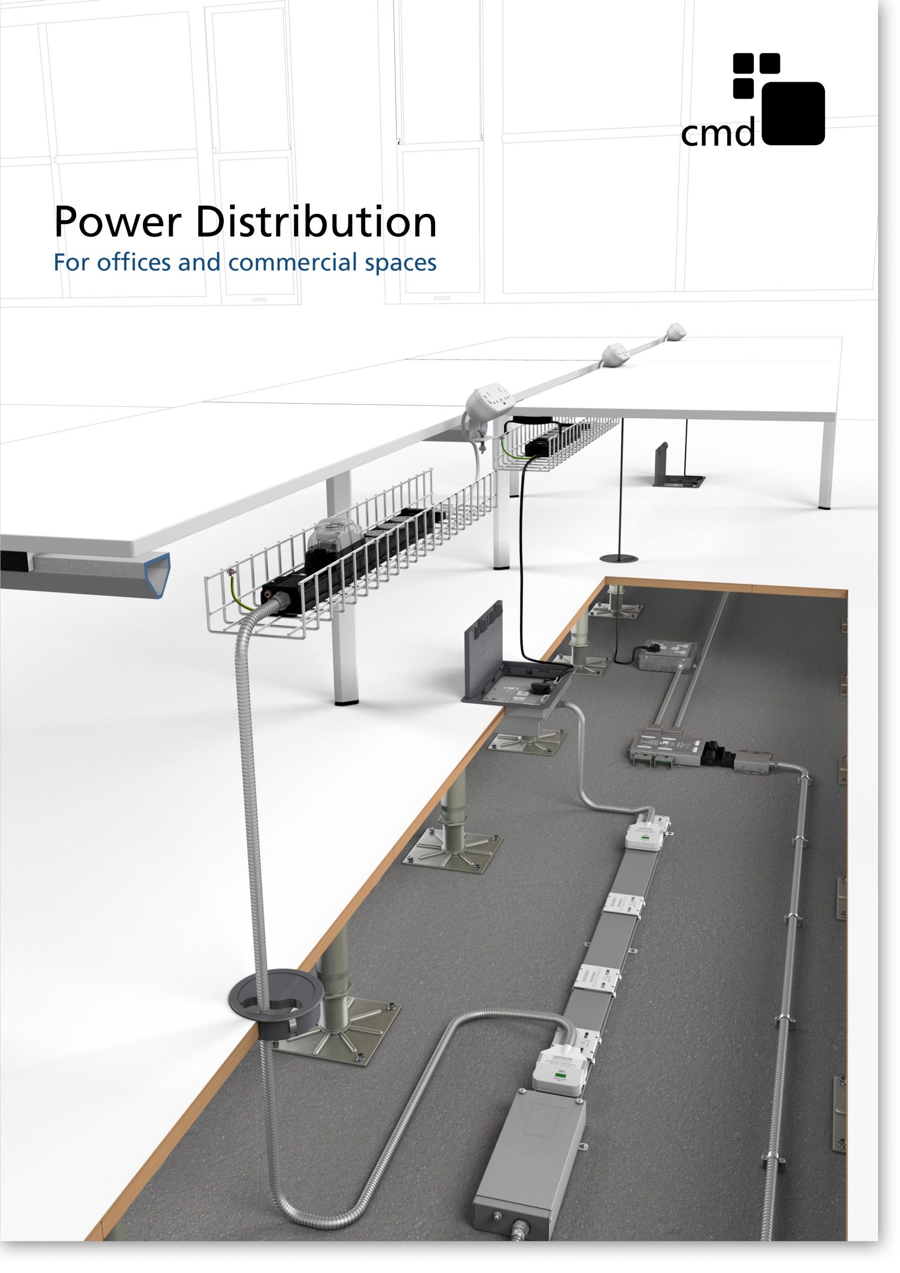
CMD Ltd has released a new catalogue, providing an easy to follow technical guide to our power distribution systems and plug and play desk modules. Detailing CMD’s full range of UK-manufactured power distribution systems and plug and play desk modules, the catalogue will be a helpful source of information to M&E engineers and contractors alike to understand how our power distribution systems connect together and...

Read more
Power Distribution Catalogue
CMD Ltd PLAYS ESSENTIAL ROLE IN ELECTRICAL FIT OUT AT LONDON’S PRESTIGIOUS OFFICE DEVELOPMENT

CMD Ltd, specialist in workplace connectivity and ergonomic solutions, has provided a flexible and high-quality power distribution network for The Ray, a prestigious office development in London’s Farringdon. Well-known for being the former site of The Guardian newspaper, The Ray now stands as an 83,000ft² office development characterised by a modernised warehouse aesthetic, with level two now occupied by a global social media company. The...

Read more

The Ray
CMD plugs in to european opportunity with Schuko Capsule unit launch

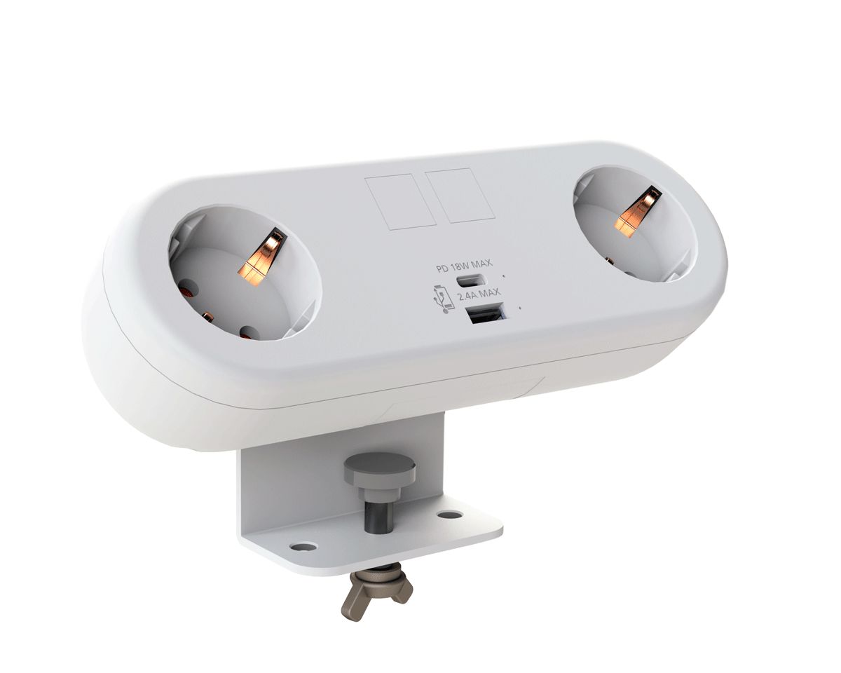
CMD Ltd, the specialist in power and connectivity solutions for commercial environments, has launched a Schuko version of its popular fixed format Capsule workstation power module for export to mainland Europe and beyond. A popular on desk power module comprising two sockets and dual USB (type A and C) chargers, CMD’s Capsule unit is already widely specified in the UK as an off-the-shelf workstation power...

Read more
CMD White Schuko Capsule Desk Power Module
CMD LTD EXTENDS MONITOR ARM RANGE WITH THE LAUNCH OF REACH PLUS

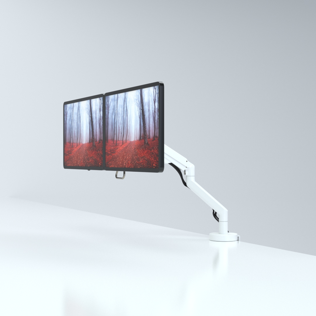
CMD Ltd, the specialist in ergonomic and connectivity solutions for commercial interiors, has completed its Reach monitor arm range with the launch of the Reach Plus. Available in single or dual screen options, the Reach Plus has been designed to provide an ideal solution for both single and dual screen workstation configurations, or can be used with next generation of large format curved screens. Suitable...

Read more
CMD Ltd DEMONSTRATES THE ART OF POWER DISTRIBUTION AT THE UNIVERSITY OF WARWICK

CMD Ltd, the specialist in workplace connectivity and ergonomic solutions, has provided Betatrak busbar power distribution and a range of electrical accessories for two major capital investment projects at the University of Warwick. Designed by Fielden Clegg Bradley Studios, the £33 million Faculty of Arts building is a showpiece development comprising four interconnected structures set around a central atrium, which will enable inter-disciplinary collaboration across...

Read more

University of Warwick
CMD BRINGS HARMONY TO COVENTRY UNIVERSITY RESEARCH FACILITIES

CMD Ltd, the specialist in power distribution solutions and workstation power and ergonomics, has provided under desk and on desk power modules for the refurbishment of three Coventry University research buildings. Located on Coventry University Technology Park, a business park designed to encourage collaboration between the university and knowledge-based businesses, the three buildings are being repurposed as office accommodation for university research teams. The refurbishment...

Read more

Coventry University

How to Choose the Best Satellite Racking System?

Choosing the best Satellite Racking system begins with the real mission, not the product brochure. A rack may support antennas, solar modules, receivers, or compact satellite equipment. Each application creates different structural demands. Weight matters. So does wind.

Dr. James Wertz, a respected spacecraft systems engineer, once put the discipline plainly: “A design is only as good as its requirements.” That principle fits Satellite Racking perfectly. Before comparing materials or prices, define the equipment load, mounting surface, vibration exposure, cable routes, service access, and expected operating life. A coastal installation may need corrosion-resistant aluminum or treated steel. A rooftop system may require careful waterproofing and wind calculations. Tight cable bend radii can quietly damage performance.

No rack is universally best. That is the uncomfortable part. A lightweight frame may simplify installation, yet flex under changing loads. A heavy frame may improve stability, yet complicate transport and maintenance. Field conditions often expose weaknesses that drawings miss. Even a clean installation can fail when drainage is blocked or fasteners loosen after repeated thermal expansion.

This guide examines those practical trade-offs. It considers structural strength, compatibility, adjustment range, grounding, weather resistance, maintenance, and total ownership cost. It also questions attractive specifications that lack independent testing. A qualified engineer should verify site-specific requirements and applicable safety standards. The goal is not the most expensive Satellite Racking system. It is the most dependable fit for the equipment, location, and people maintaining it.

How to Choose the Best Satellite Racking System?

Understanding Satellite Racking Systems and Their Main Types

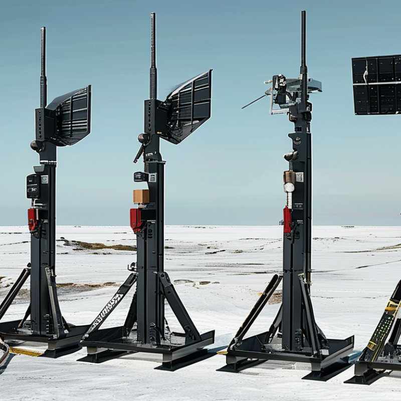
A satellite racking system supports dishes, antennas, and related equipment in a stable position. Its frame must resist wind, vibration, rain, and equipment weight. The best choice depends on the building, dish size, maintenance access, and local installation requirements. A rack that looks strong may still twist under seasonal winds.

Rooftop racks suit flat roofs and open areas with clear signals. They may use ballast or mechanical anchors, but each method affects waterproofing and structural loading. Wall-mounted systems save roof space and work well on solid masonry. Ground-mounted racks offer easier access and simpler cable routing. Pole-mounted systems provide height, although they need careful foundation design. Compact racks can fit tight spaces, but limited working room creates real maintenance problems.

During site inspections, I check the mounting surface, nearby obstructions, cable bends, drainage, and corrosion risks. Stainless or galvanized components usually perform better in wet environments. I also verify the rack’s rated load, wind resistance, fastener quality, and adjustment range. Do not ignore access.

A practical selection includes a small safety margin, not just the minimum specification. I once focused too heavily on signal clearance and underestimated service access. The installation worked, but later adjustments became awkward. That experience changed my checklist: stability matters, but so do inspection time, replacement access, and future equipment changes.

How to Choose the Best Satellite Racking System? - Understanding Satellite Racking Systems and Their Main Types

Racking System Type Typical Installation Location Compatible Dish Size Typical Height or Footprint Roof Penetration Main Advantages Main Limitations Best Use Case
Pole-Mount Rack Ground, concrete footing, or an existing structural pole Approximately 0.6–2.4 m diameter About 1.5–4.5 m above ground; footing commonly 0.6–1.2 m wide Not applicable when ground-mounted Good elevation, clear signal path, strong resistance to accidental contact, and flexible azimuth adjustment Requires excavation or a verified structural support; wind loads increase with height Large dishes, remote sites, and installations requiring obstruction clearance
Wall-Mount Rack Masonry or reinforced exterior walls Approximately 0.45–1.2 m diameter Bracket projection commonly 0.3–0.8 m from the wall No roof penetration; wall anchors are required Compact, economical, easy to access, and suitable for many residential or commercial buildings Limited by wall strength, edge distance, local wind exposure, and line-of-sight obstructions Small to medium dishes installed on structurally sound walls
Roof-Penetrating Rack Structural roof framing, equipment platforms, or roof curbs Approximately 0.6–2.4 m diameter Usually 0.3–1.5 m above the roof surface Yes; waterproof flashing and structural reinforcement may be needed High stability, precise alignment, and suitability for heavier equipment Higher installation complexity, potential leakage risk, and greater maintenance responsibility Permanent commercial, institutional, or broadcast installations
Non-Penetrating Roof Rack Flat roofs with adequate ballast capacity Approximately 0.6–1.8 m diameter Typical footprint: 1.2–2.5 m long × 1.0–2.0 m wide No Avoids roof drilling, can reduce waterproofing work, and is relatively easy to relocate Adds dead load, needs wind assessment, and may not suit steep or weak roofs Leased buildings and flat-roof installations where penetrations are undesirable
Tripod Roof Rack Pitched or flat roofs with suitable structural attachment points Approximately 0.6–1.2 m diameter About 0.6–1.5 m high; base commonly 0.9–1.8 m across Usually yes, although some versions use structural clamps Stable three-point support, good adjustment range, and broad compatibility with medium dishes Requires careful flashing or attachment; may be unsuitable for fragile roofing materials Residential and light commercial roofs with sufficient structural capacity
Ground-Frame Rack Concrete pads, driven posts, or prepared ground platforms Approximately 0.9–3.7 m diameter Typical footprint: 1.5–4.0 m long × 1.5–4.0 m wide Not applicable Excellent service access, strong load distribution, and suitability for large or multiple dishes Needs available land, site preparation, drainage consideration, and protection from vegetation or vandalism Large communication systems, campuses, and dedicated satellite ground stations
Portable or Temporary Rack Temporary field sites, events, emergency communications areas, or test locations Approximately 0.45–1.0 m diameter Folded length commonly 1.0–2.0 m; deployed footprint about 1.0–2.0 m No permanent penetration Fast deployment, easy transportation, and low site commitment Lower long-term stability, limited dish size, and greater sensitivity to movement or high winds Short-duration links, field operations, and backup communications

Selection note: The dimensions and dish-size ranges shown are typical planning values rather than universal limits. Final selection should be based on dish weight, projected wind area, local wind speed, mounting-surface strength, corrosion exposure, required look angle, cable routing, and applicable building codes.

Assessing Roof Structure, Space, Climate, and Installation Conditions

How to Choose the Best Satellite Racking System?

Assessing Roof Structure, Space, Climate, and Installation Conditions

A reliable satellite racking system begins with the roof, not the antenna.

Inspect rafters, decking, membranes, flashing, and existing penetrations. A visual check is useful, but it cannot confirm hidden rot or weakened connections. Structural calculations should follow ASCE 7-22 load provisions, including wind, snow, and seismic forces. The correct design depends on the site, roof height, exposure category, and attachment method. Do not treat a small dish as automatically low risk.

Space also affects signal quality and maintenance access.

Measure the antenna diameter, bracket swing, cable route, and clearance from parapets. Leave room for tools and future repairs. Tight layouts often create sharp cable bends and blocked service paths. A clean drawing can still conceal a difficult installation.

Climate data deserves equal attention.

NOAA’s 1991–2020 Climate Normals provide local wind, precipitation, temperature, and snowfall records. Use those figures with the building’s exposure conditions, rather than relying on regional averages. Coastal air may accelerate corrosion, while freeze-thaw cycles can loosen poorly sealed fasteners. In hot climates, roof surfaces can exceed ambient temperatures substantially. Material compatibility matters.

Installation conditions are less glamorous.

They matter greatly. Check roof access, lifting limits, fall protection, drilling restrictions, and weather windows. Ballasted systems may reduce penetrations, but they add dead load and can shift under extreme wind. Penetrated mounts can improve restraint, yet poor flashing creates leaks. The first layout is rarely perfect. Recheck it with the installer, structural reviewer, and roofing professional before drilling.

Comparing Materials, Load Capacity, Adjustability, and Durability

Choosing the best satellite racking system starts with material selection. Aluminum is lightweight and naturally corrosion resistant, while galvanized steel offers greater stiffness under heavy wind loads. The International Aluminium Institute reports that nearly 75% of all aluminum ever produced remains in use, supporting its long service potential. However, aluminum can deform if engineers underestimate point loads.

Load capacity must reflect real conditions, not only equipment weight. Include wind pressure, snow, vibration, cable tension, and maintenance loads. ASCE 7-22 provides recognized procedures for wind and snow-load calculations. A rack supporting a 40-kilogram antenna may experience several times that force during gusts. I have seen installations fail at brackets, not beams. That detail is easy to miss.

Adjustability improves alignment and future maintenance. Slotted holes, hinged supports, and multiple tilt positions help technicians correct uneven roofs or changing signal angles. Avoid excessive movement; loose joints create vibration and fatigue. IRENA’s Renewable Capacity Statistics 2025 recorded 1,865 GW of global solar capacity at the end of 2024, showing how rapidly outdoor mounting systems are being deployed. Durability therefore deserves equal attention. Use compatible fasteners, sealed interfaces, drainage paths, and coatings suited to the site’s corrosion category. A coastal rack may need stronger protection than an inland rack. No design is perfect. Field inspection still matters.

Evaluating Mounting Methods, Safety Features, and Maintenance Needs

Choosing the best satellite racking system begins with its mounting method. Roof-mounted frames save ground space, but they must distribute weight across suitable structural points. Ground racks offer easier access and flexible positioning, although they need stable foundations and clear surroundings. Wall mounts can work well for smaller antennas when the surface can resist wind loads. Measure twice.

A professional evaluation should check load paths, fastener strength, tilt adjustment, and local structural requirements. Some sites look suitable during installation but develop movement after heavy wind or repeated temperature changes. That risk deserves attention. Safety features should include locking hardware, protected cable routes, rounded edges, and safe technician access. Corrosion-resistant materials help, especially near coastal air or industrial moisture. Cable loops should not hang where water can collect.

Maintenance needs often decide the real cost. Inspect bolts, brackets, seals, and support surfaces at planned intervals. Check for rust, cracks, loose connections, and unusual antenna movement. After severe weather, perform an additional inspection. Cleaning may improve signal reliability, but aggressive tools can damage protective coatings. Access matters. A rack that requires awkward climbing may discourage proper servicing. I would rather choose a slightly more accessible design than save money on installation and regret it later. Even experienced installers can underestimate future maintenance time.

Selecting a System Based on Budget, Compatibility, and Future Expansion

How to Choose the Best Satellite Racking System?

Selecting a System Based on Budget, Compatibility, and Future Expansion

Budget should guide the decision, not control it. A low-cost rack may require extra adapters, stronger anchors, or later replacement. Compare the complete installation cost, including hardware, labor, cable routing, and maintenance access. A simple spreadsheet can expose hidden expenses. Leave room for professional inspection, especially on exposed roofs or elevated structures.

Compatibility begins with accurate measurements. Check the dish diameter, mounting pole size, equipment weight, and available fixing points. Confirm that the rack supports the expected wind and weather conditions. Inspect the surface closely; cracked concrete, thin metal, or aging timber can change the entire plan. Cable openings also matter. Poor routing can create water entry and difficult repairs. Small details often decide whether installation feels solid.

Future expansion deserves attention before the first bracket is tightened. Choose a rack with spare mounting positions and adjustable angles when possible. Reserve clear space for additional receivers, larger equipment, or upgraded cabling. Avoid filling every available section. That seems efficient, but it can make later work awkward and expensive. I would still question every “future-ready” claim, because extra capacity can raise today’s cost without being used. Review the system with a qualified installer and request written load data, compatibility notes, and an access plan.